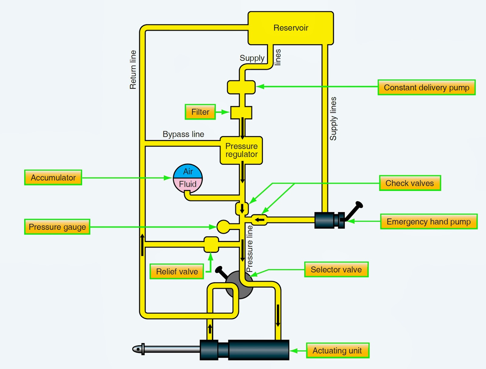
Hydraulic Control System Block Diagram Solenoid Diverter 12v
Hydraulic system block diagram Block diagram for hydraulic system Block diagram presentation of the pump and hydraulic system control
conceptual block diagram of hydraulic circuit system. | Download
Reservoir bootstrap Hydraulic schematics schematic valves iso Block diagram of hydraulic supports electro-hydraulic control system
Hydraulic pressure reducing valve symbol
Mariners repository: hydraulics part 1Hydraulic control blocks Hydraulic system block diagramHydraulic splitter log schematic diagrams systems hydraulics technical tractor wood terminology front end power result formulas build garden farm choose.
Block diagram of the hydraulic system.Valve hydraulic control diagram directional way circuit position basic Monoblock hydraulic directional control valve, 2 spool w/ dual floatBlock diagram of hydraulic control system where i u , f u --input and.

The hydraulic system block diagram.
Simple schematic diagram of hydraulic system ~ switch wiring diagramBasic hydraulic system circuit diagram Hydraulics systems diagrams and formulasThe block diagram of the control system for the hydraulic manipulator.
Hydraulic reservoirHydraulic directional spool gpm monoblock float hydraulics valves p40 detent p80 Block diagram of hydraulic supports electro-hydraulic control systemHydraulic system circuit application advantages parts introduction disadvantages learnmech.

Block diagram of hydraulic control system where i u , f u --input and
Block system diagram hydraulic train power valve elevation figure gunners tpubHydraulic circuit (system) Hydraulic pks blocks servis spolBlock diagram of hydraulic system.
Hydraulic electroHydraulic system symbols drawing engineering circuit pump mechanical simple diagram beginners fluid electrical basic cnc cylinder controlled flow pnuematic electrically Way valves two valve spool control three four flow direction drawing pressure rotary port hydraulics ports repository mariners permitting configurationsSolenoid diverter 12v selector valves hydraulics.

Wiring diagram for hydraulic solenoid
Hydraulic schematic for log splitterHydraulic pks servis spol Hydraulic system for beginnersSystem control hydraulic block diagram.
Basic hydraulic schematicsHydraulic system block diagram Control system: introduction to control systemBlock diagram of the hydraulic system control logic..

Block diagram of the hydraulic control system
Hydraulic circuit diagram// 4 way 3 position directional control valveWinch hydraulics hydraulic formulas terminology deere crane mfg truck loader relief directional valves powered Hydraulic control blocksBlock diagram of the hydraulic control system.
Hydraulic unloading valve circuit operationHydraulic control system Hydraulic valve unloading circuit drawing operation control relief accumulator pressure check operated paintingvalleyConceptual block diagram of hydraulic circuit system..

Electro supports
Principle diagram of hydraulic control system of test bench. 1: tank .
.


Basic Hydraulic System Circuit Diagram

Block diagram presentation of the pump and hydraulic system control

basic hydraulic schematics | Diigo Groups
HYDRAULIC CIRCUIT DIAGRAM// 4 WAY 3 POSITION DIRECTIONAL CONTROL VALVE
Mariners Repository: Hydraulics Part 1 - Direction Control Valves

Hydraulic system block diagram | Download Scientific Diagram